
Raspberry Pi 5 Power Stability Issue: Investigation & Resolution

We run a Raspberry Pi 5 as the edge compute unit in one of our embedded systems. The setup involves a mmWave radar sensor, a camera module, and several concurrent software services handling data ingestion, communication, and real-time inference. Under full load, the Pi kept shutting down, every single time, without fail. This is how we fixed it over two days of experimentation.
The Setup
The Pi 5 sits at a ceiling mount, meaning the power cable run from the supply to the board is longer than a typical bench setup. The supply is a 300W industrial unit with a regulated 5V output, more than capable on paper.
The system runs several services concurrently:
- A sensor acquisition service reading data over USB serial
- A camera capture service
- A communication agent handling data routing
- A real-time inference engine performing signal processing and classification
At idle and even under partial load, everything ran fine. The problem appeared the moment the inference engine, the most compute-intensive service, was started on top of everything else already running.
The Problem
The instant the inference engine started, the Pi shut down. Not after a few minutes of running hot, it shut down immediately, every single time. No graceful shutdown, no warning, just off.
The obvious suspect was power. The Pi 5 requires a stable 5.1V at 5A for full operation. Its PMIC (Power Management IC) monitors the input rail; when the voltage drops below roughly 4.63V, it triggers undervoltage protection, and the board shuts down.
What was happening is that the inference engine’s startup created a sharp, instantaneous current spike on top of the already elevated baseline draw from the sensor, camera, and running services. The supply couldn’t respond fast enough, especially over a long cable with non-trivial resistance, and the rail collapsed momentarily, taking the Pi with it.
We measured the rail dropping as low as 4.6V to 4.7V during the spike. That is well below the threshold.
Experiment 1: Raise the Supply Voltage (Day 1)
Hypothesis: The long cable run was introducing enough resistive drop that the Pi was already receiving less than 5V before the spike even hit. Pre-compensating by raising the supply output would give more headroom.
What we did: Increased the supply output slightly above 5V.
Result: Same failure. The Pi shut down the moment the inference engine started.
What we learned: Cable resistance was a contributing factor but not the root cause. The transient spike was happening faster than the supply’s regulation loop could respond to, regardless of the baseline voltage level. We needed something that could react in microseconds, not milliseconds.
Experiment 2: Add a Capacitor Bank (Day 2, Step 1)
Hypothesis: Capacitors placed directly at the Pi’s power input would act as a local energy reservoir, supplying the instantaneous current surge before the supply could react over the long cable.
What we did: Wired three electrolytic capacitors in parallel across the power rail at the Pi’s input:
| Capacitor | Value |
|---|---|
| C1 | 4700 µF |
| C2 | 10 µF |
| C3 | 0.2 µF |
Figure 1: Schematic of the power supply, cable resistance, and parallel capacitor bank connected to the Raspberry Pi 5 power input
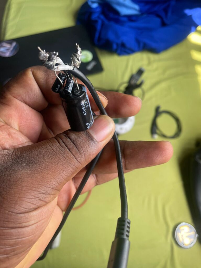
Figure 2: Physical capacitor bank (4700 µF, 10 µF, 0.2 µF electrolytic, in parallel) wired inline between the supply output and the Pi 5 USB-C power input
Result: Improvement: the inference engine ran for several seconds before the Pi eventually shut down. Not a solution, but a clear sign we were on the right track.
What we learned: Local energy storage works. The capacitor bank was absorbing the initial spike and buying time, but the bulk charge wasn’t enough to carry the Pi through the full startup transient of the inference engine on its own.
Note on capacitor choice: All three capacitors here are electrolytic. Electrolytics have relatively high equivalent series inductance (ESL), which means they are most effective in the millisecond range and lose effectiveness at higher frequencies. For a more complete solution in a production design, a mixed bank; bulk electrolytic for slow transients plus ceramic capacitors for fast nanosecond-range spikes, would be more appropriate. For our purposes the electrolytics were sufficient as part of a combined approach.
Experiment 3: Disable USB-C PD Negotiation (Day 2, Step 2)
Hypothesis: The Pi 5 uses USB Power Delivery negotiation to determine what the connected supply can provide. With a custom DC supply rather than a PD-compliant charger, the Pi can’t confirm 5A availability and conservatively limits its own current draw. Disabling this would remove that artificial ceiling.
What we did: Added the following to /boot/firmware/config.txt:
usb_max_current_enable=1
This tells the Pi to always assume a 5A capable source is connected, skipping the conservative fallback behaviour.
Result: Interestingly, the Pi shut down earlier than with the capacitor bank alone. We did not fully investigate why at the time, but the likely explanation is that removing the current limit allowed the inference engine to draw more aggressively at startup, producing a larger spike than the capacitor bank could absorb on its own.
What we learned: Disabling PD negotiation alone, or paired only with the capacitor bank, was not sufficient. But it remained part of the configuration going forward, as it removes an artificial software-imposed constraint on current draw.
Experiment 4: Raise Voltage to 5.5V (Day 2, Step 3)
Hypothesis: With capacitors handling local transient buffering and PD negotiation disabled, raising the supply voltage to 5.5V would provide enough headroom that even under the worst-case transient drop along the cable and at the board, the rail would stay above the 4.63V threshold.
What we did: Adjusted the supply output to 5.5V, with the capacitor bank and usb_max_current_enable=1 still active.
Observable side effect: The supply’s cooling fan spun noticeably louder and faster than at any point in previous testing: a sign the unit was working harder than before.
Result: Everything ran. Sensor, camera, all services, and the inference engine: simultaneously, without the Pi shutting down. Stability held through extended testing of the full pipeline.
The Fix
The combination of all three changes achieved stable operation:
| Change | Purpose |
|---|---|
| Capacitor bank (4700 µF + 10 µF + 0.2 µF in parallel) | Local energy reservoir to absorb instantaneous current spikes |
usb_max_current_enable=1 in /boot/firmware/config.txt | Remove conservative current limiting from failed PD negotiation |
| Supply voltage raised to 5.5V | Provide voltage headroom to survive transient drops along the cable |
Verifying the Fix
After any reboot, confirm the configuration is holding:
# Confirm PD override is active
vcgencmd get_config usb_max_current_enable
# Expected: usb_max_current_enable=1

# Check for undervoltage or throttling
vcgencmd get_throttled
# Expected: throttled=0x0
A non-zero value from get_throttled means the Pi is seeing undervoltage: check your supply and wiring before continuing.
To stress-test the setup:
stress-ng --cpu 4 --io 2 --vm 2 --vm-bytes 128M --timeout 60s
Monitor voltage and temperature live in a second terminal:
watch -n 1 "vcgencmd measure_volts; vcgencmd measure_temp"
Important Caveats
5.5V is above spec. The Pi 5’s nominal input is 5.1V. We have not seen damage at 5.5V during testing, but running above spec over extended periods carries real risk, with gradual degradation of the PMIC and onboard capacitors being the main concern. If you replicate this, do so with that risk in mind and monitor the board’s behaviour over time.
The three changes were not individually isolated. We confirmed stability with all three active, but did not go back to test which subset is actually necessary. Fewer than three changes may be sufficient. If you want to find the minimum required configuration, remove one change at a time and stress-test after each removal before concluding.
Powering via GPIO instead of USB-C removes onboard protection. If you ever power the Pi through the GPIO header (Pin 2 or 4 for 5V, Pin 6 for GND) rather than the USB-C port, be aware that this path bypasses the polyfuse and overvoltage protection. At 5.5V, a fault could cause permanent board damage. Use an inline fuse if going that route.
Takeaway
The Pi 5 shutting down under sudden load spikes is not a rare problem; it comes up regularly in projects that push the board hard with multiple concurrent services. The fix is rarely one thing. In our case, it took local capacitive buffering to handle the transient, a config change to remove artificial current limiting, and enough voltage headroom to survive the drop. Any one of those alone was not enough.
If your Pi is shutting down the moment a compute-heavy process starts, start by measuring your rail voltage under load. If it’s dipping below 4.63V, you have a power delivery problem, and the approach described here is one way to solve it.
Have you run into Pi 5 power issues on a demanding project? Share what worked for you in the comments.